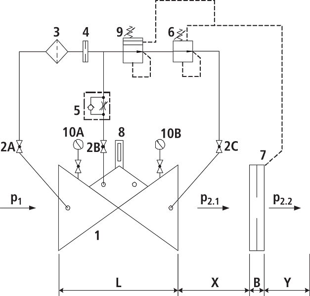
Components
- 1: Main valve
- 2: Ball valve (A, B, C)
- 3: Filter
- 4: Orifice
- 5: Throttle check valve
- 6: Control valve differential pressure measurement
- 7: Differential pressure orifice plate
- 8: Optical position indicator (optional: Electrical position indicator, opening limiter)
- 9: Control valve pressure reduction
- 10: Manometer with ball valve (A, B)
- B: DN 40 to DN 150: 22 mmDN 200 to DN 250: 27 mmDN 300 to DN 400: 29 mm
- X: 5 x DN line
- Y: 3 x DN line
| Article No. | DN | PN (bar) | L (mm) | weight (kg) | Availability | watchlist |
|---|---|---|---|---|---|---|
| 1302007000 | 1 1/2" | 16 | 210 | 11.000 | on demand | |
| 1302008000 | 2" | 16 | 210 | 11.000 | on demand | |
| 1302040000 | 40 | 16 | 200 | 15.750 | on demand | |
| 1302050000 | 50 | 16 | 230 | 16.250 | on demand | |
| 1302065000 | 65 | 16 | 290 | 21.300 | on demand | |
| 1302080000 | 80 | 16 | 310 | 27.400 | on demand | |
| 1302080025 | 80 | 25 | 310 | 27.400 | on demand | |
| 1302100000 | 100 | 16 | 350 | 35.400 | on demand | |
| 1302125000 | 125 | 16 | 400 | 51.500 | on demand | |
| 1302150000 | 150 | 16 | 480 | 76.000 | on demand | |
| 1302200000 | 200 | 10 | 600 | 114.600 | on demand | |
| 1302200016 | 200 | 16 | 600 | 114.600 | on demand | |
| 1302250000 | 250 | 10/16 | 730 | 247.000 | on demand | |
| 1302300000 | 300 | 10/16 | 850 | 358.000 | on demand |
DN
watchlist
| 1302007000 | 1 1/2" | |
| PN | 16 bar | |
| L | 210 mm | |
| weight | 11.000 kg | |
| Availability | on demand | |
| 1302008000 | 2" | |
| PN | 16 bar | |
| L | 210 mm | |
| weight | 11.000 kg | |
| Availability | on demand | |
| 1302040000 | 40 | |
| PN | 16 bar | |
| L | 200 mm | |
| weight | 15.750 kg | |
| Availability | on demand | |
| 1302050000 | 50 | |
| PN | 16 bar | |
| L | 230 mm | |
| weight | 16.250 kg | |
| Availability | on demand | |
| 1302065000 | 65 | |
| PN | 16 bar | |
| L | 290 mm | |
| weight | 21.300 kg | |
| Availability | on demand | |
| 1302080000 | 80 | |
| PN | 16 bar | |
| L | 310 mm | |
| weight | 27.400 kg | |
| Availability | on demand | |
| 1302080025 | 80 | |
| PN | 25 bar | |
| L | 310 mm | |
| weight | 27.400 kg | |
| Availability | on demand | |
| 1302100000 | 100 | |
| PN | 16 bar | |
| L | 350 mm | |
| weight | 35.400 kg | |
| Availability | on demand | |
| 1302125000 | 125 | |
| PN | 16 bar | |
| L | 400 mm | |
| weight | 51.500 kg | |
| Availability | on demand | |
| 1302150000 | 150 | |
| PN | 16 bar | |
| L | 480 mm | |
| weight | 76.000 kg | |
| Availability | on demand | |
| 1302200000 | 200 | |
| PN | 10 bar | |
| L | 600 mm | |
| weight | 114.600 kg | |
| Availability | on demand | |
| 1302200016 | 200 | |
| PN | 16 bar | |
| L | 600 mm | |
| weight | 114.600 kg | |
| Availability | on demand | |
| 1302250000 | 250 | |
| PN | 10/16 bar | |
| L | 730 mm | |
| weight | 247.000 kg | |
| Availability | on demand | |
| 1302300000 | 300 | |
| PN | 10/16 bar | |
| L | 850 mm | |
| weight | 358.000 kg | |
| Availability | on demand | |
Physical characteristics
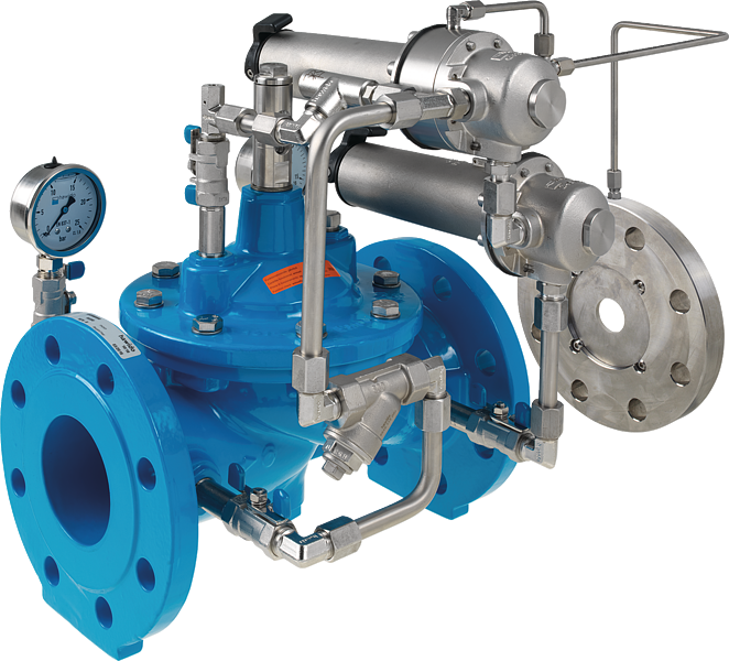
- The main valve is a hydraulically operating diaphragm valve. The work energy is the inherent medium.
- Most valve types operate purely hydraulically without any foreign energy.
Application
- To use in drinking water systems (other media after consultation)
- Limitation of the inflow from a pressure zone into a lower pressure zone
- Constantly maintaining a filter flow
- The supply to a secondary network necessitates a limitation of the flow, so as to not endanger, for example, the extinguishing reservoir of the primary network (in combination with a reduction in pressure).
Mode of operation
- The flow–control valve completely hydraulically ensures a pre–determined maximum flow, irrespective of any changes in the operating pressure. The nominal flow rate can be progressively varied up to ±15% via the control valve. The inlet pressure is reduced to a constant outlet pressure downstream of the orifice plate.
Product information
- To calculate the dimensions of the valve please refer to the following information:
- Maximum and minimum inlet pressure (static and dynamic pressure ratios)
- Required outlet pressure after the orifice plate
- Required flow rate
- Permissible loss of pressure incl. measuring orifice (usually 0.5 bar over the valve and orifice plate)
- Available line diameters and lengths
- Construction of the valve (straight or angle design)
- For the calculation basis, information on the loss of pressure and the characteristic values of the valve, please refer to the end of Chapter E.
Design
- Design according to DIN EN 1074
- Construction length acc. to DIN EN 558
- Flange mass according to DIN 1092-2, to PN 25 DN 300
- Pressure levels: PN 10 or PN 16 to DN 300, PN 25 to DN 200, higher pressures on request.
- Nominal widths DN 50, DN 80, DN 100 and DN 150 available in angular design
- Nominal widths 1 ½" and 2" with threaded connection (female thread)
- Medium temperature up to 40°C
Installation and assembly
- Shut–off valves should be fitted on both sides of the valve and a dirt trap should be installed on the inlet side of the valve. Depending on the installation situation, a mounting/dismounting adapter and an aeration and ventilation system should be provided.
- The orifice plate must be installed after the valve. It is recommended that the following measurements are taken into consideration:
- X = 5 x DN, distance between the valve and the orifice plate in a straight line
- Y = 3 x DN, distance after the orifice plate and the shut–off component, in a straight line
Vantages
- Maintenance-free, non-rusting valve seat
- Pressed-in seat
- EWS-coating according to RAL GSK
more
