
| Article No. | DN | PN (bar) | L (mm) | weight (kg) | Availability | watchlist |
|---|---|---|---|---|---|---|
| 1515040000 | 40 | 10/16 | 200 | 17.000 | on demand | |
| 1515050000 | 50 | 10/16 | 230 | 17.500 | on demand | |
| 1515065000 | 65 | 10/16 | 290 | 22.600 | on demand | |
| 1515080000 | 80 | 10/16 | 310 | 28.600 | on demand | |
| 1515100000 | 100 | 10/16 | 350 | 36.600 | on demand | |
| 1515125000 | 125 | 10/16 | 400 | 52.600 | on demand | |
| 1515151000 | 150 | 10/16 | 480 | 76.000 | on demand | |
| 1515200010 | 200 | 10 | 600 | 115.700 | on demand | |
| 1515200016 | 200 | 16 | 600 | 115.700 | on demand | |
| 1515250000 | 250 | 10/16 | 730 | 249.000 | on demand | |
| 1515300010 | 300 | 10/16 | 850 | 360.000 | on demand |
DN
watchlist
| 1515040000 | 40 | |
| PN | 10/16 bar | |
| L | 200 mm | |
| weight | 17.000 kg | |
| Availability | on demand | |
| 1515050000 | 50 | |
| PN | 10/16 bar | |
| L | 230 mm | |
| weight | 17.500 kg | |
| Availability | on demand | |
| 1515065000 | 65 | |
| PN | 10/16 bar | |
| L | 290 mm | |
| weight | 22.600 kg | |
| Availability | on demand | |
| 1515080000 | 80 | |
| PN | 10/16 bar | |
| L | 310 mm | |
| weight | 28.600 kg | |
| Availability | on demand | |
| 1515100000 | 100 | |
| PN | 10/16 bar | |
| L | 350 mm | |
| weight | 36.600 kg | |
| Availability | on demand | |
| 1515125000 | 125 | |
| PN | 10/16 bar | |
| L | 400 mm | |
| weight | 52.600 kg | |
| Availability | on demand | |
| 1515151000 | 150 | |
| PN | 10/16 bar | |
| L | 480 mm | |
| weight | 76.000 kg | |
| Availability | on demand | |
| 1515200010 | 200 | |
| PN | 10 bar | |
| L | 600 mm | |
| weight | 115.700 kg | |
| Availability | on demand | |
| 1515200016 | 200 | |
| PN | 16 bar | |
| L | 600 mm | |
| weight | 115.700 kg | |
| Availability | on demand | |
| 1515250000 | 250 | |
| PN | 10/16 bar | |
| L | 730 mm | |
| weight | 249.000 kg | |
| Availability | on demand | |
| 1515300010 | 300 | |
| PN | 10/16 bar | |
| L | 850 mm | |
| weight | 360.000 kg | |
| Availability | on demand | |
Physical characteristics
- The main valve is a hydraulically operating diaphragm valve. The work energy is the inherent medium.
- Most valve types operate purely hydraulically without any foreign energy.
Application
- In combination with a PLC controller, different time–dependent target pressure values, for example, can be set This application can be used for lowering the pressure during the night or for setting up a higher extinguishing pressure.
Mode of operation
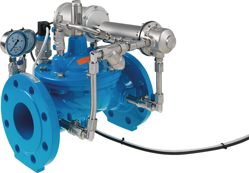
- The pressure reducing valve with motor–driven pilot valve reduces a variable inlet pressure (p1) to a constant lower outlet pressure (P2). Fluctuating flow rate and inlet pressure have no effect on the outlet pressure controlled by the control valve. The outlet pressure (p2) is adjustable in the range from 1.5 to 12 bar.
Product information
- To calculate the dimensions of the valve please refer to the following information:
- Maximum and minimum inlet pressure (static and dynamic pressure ratios)
- Pressure levels and time zones
- Desired outlet pressure
- Maximum and minimum flow rates
- Possible requirement for extinguishing water
- Available line diameters and lengths
- Construction of the valve (straight or angle design)
- For the calculation basis, information on the loss of pressure and the characteristic values of the valve, please refer to the end of Chapter E.
Design
- Design according to DIN EN 1074
- Construction length acc. to DIN EN 558
- Flange mass according to DIN 1092-2, to PN 25 DN 300
- Druckstufen: PN 10 oder PN 16 bis DN 300; PN 25 bis DN 200
- Nominal widths DN 50, DN 80, DN 100 and DN 150 available in angular design
- Nominal widths 1 ½" and 2" with threaded connection (female thread)
- Medium temperature up to 40°C
Installation and assembly
- Shut–off valves should be fitted on both sides of the valve and a dirt trap should be installed on the inlet side of the valve. Depending on the installation situation, a mounting/dismounting adapter and an aeration and ventilation system should be provided.
Vantages
- Maintenance-free, non-rusting valve seat
- Pressed-in seat
- Counter-seat with optimised geometry
- EWS coating according to RAL GSK (coating thickness: min. 250 µm)
- Optical position indicator in stainless steel, including vent screw built onto the valves as standard (except Open/Close and float valves).
- Control line: Fittings and piping in stainless steel.
- Control line: Connection with the clamping ring can be dismounted radially. No protruding pipe end after the clamping ring.
- The necessary shut-off elements are available in the control line as standard. The ball valves are made from stainless steel and have a short handle. No long actuating lever.
- The necessary pressure gauge is built in as standard, and can always be shut off with a ball valve (replacement of the pressure gauge possible without having to shut down the system).
- Dirt trap in the control line installed horizontally for flawless functioning and cleaning. The dirt does not fall back when cleaning the filter screen.
- Pilot valve manually adjustable without requiring a tool.
- DVGW and SVGW approvals
more
